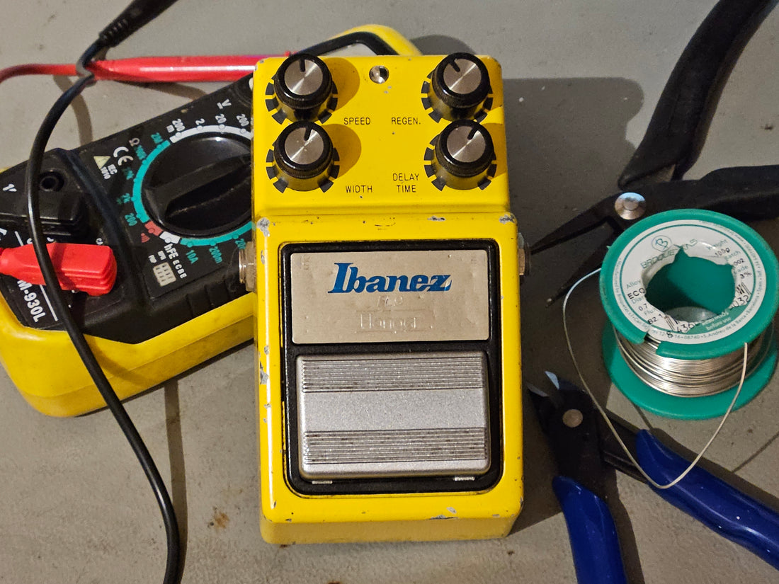
A flanger which does not flange
Vintage pedals often sound amazing, but the old electronics are slowly degrading over time. In this case, the characteristic "woosh" sound was no where to found in this vintage Ibanez FL9 Flanger. The rest worked fine. In this blog you will read how to fix this problem based on years of experience and over twenty repaired FL9s.
At first glance

Initially, all looks well on the board. No clear signs of distress or debris is visible. However, when zooming in, some discoloration is visible at the middle of the board, towards the left.

When flipping over the board, two orange components are seen. 
From experience, these 47uF capacitors tend to leak due to aging. 40 years being inside a pedal has taken their toll; they spill their guts. They however are important, as they are part of the LFO, the low frequency oscillator. That's a sinus-wave being generated which in turn 'moves' the wooshing sound, simply stated. No wonder our flanger was not flanging properly!


Clearly, these don't look fresh anymore. We got this one just in time, keeping them in will cause the circuit board to be eaten away from the toxic acid chemicals inside the capacitors.

After removal, don't forget to clean up the board. Use flux cleaner or equivalent prior to fitting replacement parts. And a gentle brushing action. Do not force it or you will lift off the pads on the board. Let the cleaner do its work.
The old caps were 47uF rated for 10 volt. We replaced these with 25 volt rating. A note on capacitors: Always keep the same capacitance, but you can safely upgrade the capacitors to a higher voltage rating. Never insert a lower voltage inside a pedal, e.g. a 16 volt rating in a 18 volt pedal. These will explode. A 25 volt capacitor in a 9 volt pedal, that's fine.
After replacing these two capacitors with fresh ones, it is time to test. Unfortuantely, it still wasn't flanging correctly. Back to the board....
Another suspect
At the upper left corner, a dodgy discoloration was seen from the component-side. Note that the capacitor has greenish crystals at its lugs; clearly a faulty component. It is in the 4.5 volt line, the one that sets the bias to the chips.

Calibrating
Now the pedal is in working condition again, listen carefully. In our case, the LFO-signal sounded a bit jagged. Some gentle adjustments on the BIAS knob can synchronize the movement again, so there is no hump in the sinus-signal coming from the LFO. Use a flathead mini screwdriver in to adjust. Small movements, sharp ear.

Concluding
Three capacitors (3x 47uF), one in the 4.5 volt line and two in the LFO section, prevented this pedal from firing up properly. Remember the traces are fragile especially now they have been corroded due to the acid from the capacitors. If you are careful, this is a job you can do yourself. Use a soldering station with temperature control (put it on roughly 350 deg C), use a desoldering pump to suck away the solder and clean the board. Insert your new capacitors and you might just have saved your pedal. Else, we are here to help! Reach out to us and we will see what we can do for you.